Block Diagram
You have required floorplan drawing database information files (*.EDB) added in Output Manager list.
-
Select utility.
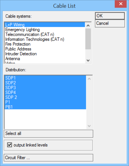
Opens the Cable List dialog.
- Cable systems — Select Cable System for Cable List.
- Distribution — Select Distributions in Cable Systems. Multiple selection available, use <Shift>-mouse click and <Ctrl>-mouse click.
- Output linked levels — Check to activates cabling through different floorplans (Model link) in Cable List.
- Circuit Filter — Opens the Filter Circuits/Lines dialog. Select Circuits/Lines for Block Diagram.
-
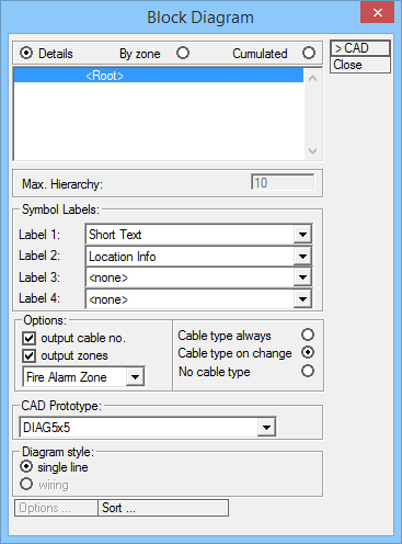
Click OK to opens the Block Diagram dialog.
- Basic options — select one of the options to define block diagram structure:
- Max. Hierarchy — Default: 10, not editable.
- Label 1, 2, 3, 4 — Set labels for symbols in Block Diagram, in each level.
Options available:
- Options — Set options to define zone and draw cable type in block diagram.
- Output cable no. — when checked, the cable number are shown in block diagram.
- Output Zones — when checked, allows selecting one of the zones options: The selected zones are then shown in block diagram.
- Cable type always — when checked, cable types are shown in block diagram.
- Cable type on change — when checked, cable types are shown in block diagram only when cable type changes.
- No cable type — when checked, No cable types are shown in block diagram.
- CAD Prototype — Select CAD prototypes with different sizes:
- Diagram style — check desired style for block diagram:
- Sort — Opens the Diagram Sort dialog.
Used to sorts order of Circuits/Lines for Block Diagram.
- Diagram Sort listview — Lists Distributions.
- Circuit/Line listview — Displays Circuits/Lines for selected distribution.
 — Select Circuit/Line in the listview , click on up- or down arrow to change it's place in hierarchy for block diagram.
 - OK — Closes the Diagram Sort dialog and accepts selected changes.
- Click >CAD to create the Block Diagram with selected settings/options. Electrical discipline automatically places the Block Diagrams according to Design Files section (see below).